
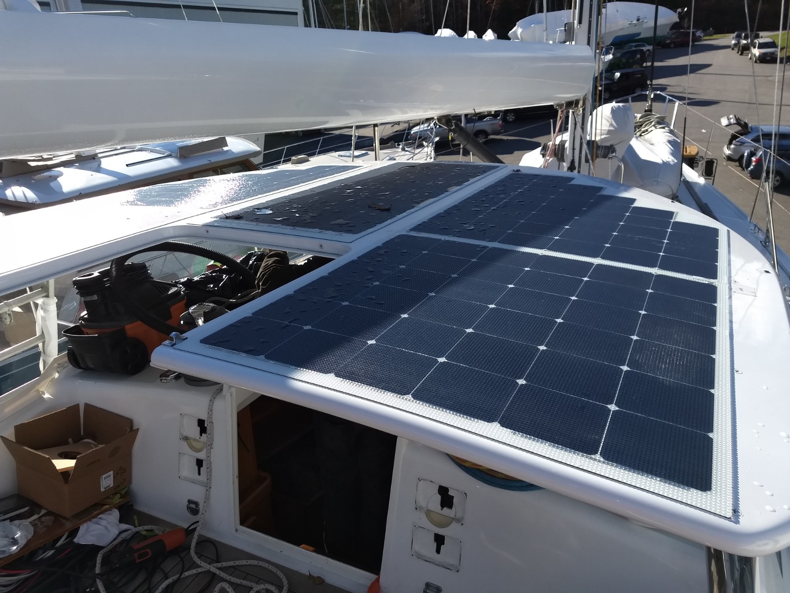
INTRODUCTION
Thank you for purchasing a Solbian product. This manual covers the Solbian panels made in Italy (SP, SR & SXp series) as well as the SR+ panels, which are manufactured by Merlin Solar based in San Jose, CA. Our photovoltaic modules are built using innovative technology and superior quality materials. They will supply your energy needs in the harshest environmental conditions and with the versatility to suit many different applications.
Please read these instructions carefully, to ensure correct utilization and a long product life.
This manual is not an explicit or implicit warranty. Solbian accepts no responsibility for damage caused by the installation, use and maintenance of its products. Solbian reserves the right to modify its products, the technical specifications, and this installation manual without notice. (For a warranty summary, see pages 15-16)
THE FOLLOWING INSTRUCTIONS ARE EXCLUSIVELY GENERAL ADVICE. WE RECOMMEND THAT YOU HAVE THE MODULES INSTALLED BY QUALIFIED TECHNICIANS, RESPECTING STANDARDS IEC 62548 AND 62257 AND/OR ABYC ELECTRICAL RECOMMENDATIONS. WE RECOMMEND THAT YOU CONTACT YOUR SOLBIAN DEALER FOR DETAILS CONCERNING TECHNICAL ASSISTANCE.
Please keep the original receipt of purchase for the duration of the warranty.
WARNINGS & PRECAUTIONS
The following instructions must be read carefully and fully understood before proceeding with the installation, connection, and use of Solbian modules. Contact with electrical components, such as terminals, can cause burns and electric shock even when the module has not yet been connected to an electrical circuit. A photovoltaic module generates electricity as soon as it is exposed to the sun or to a source of light. Although the electrical output of one single Solbian module is not dangerous, the connection of several modules in series or in parallel increases respectively the voltage and current. A photovoltaic system consisting of several modules can therefore generate voltages and currents which are dangerous and could be lethal. SOLBIAN will not be held responsible in any way for accidents and damage to persons, including electric shock, caused by incorrect use or installation.
- Check the compatibility of the charge regulator (if purchased separately) with Solbian products.
- Do not modify the electrical connections of the modules, and do not open or remove the sealed Junction Box (JB) which joins the internal structure of the module to the external electrical connections.(unless doing a JB repair, p.18)
- Do not cut or pierce the module, this could cause live components to be exposed and/or damage the module.
- Do not expose the photovoltaic module to direct light during installation of the system and in any case take care when the module is exposed to light. It produces current and therefore its terminals are electrically live.
- The maintenance, installation, and removal of the photovoltaic modules must take place on dry surfaces. Use exclusively tools with insulated grips.
- Do not use photovoltaic modules in the presence of flammable or explosive substances. Keep the modules in their original packaging up to the moment of their installation.
- Ensure that the position of the photovoltaic modules does not cause mechanical or electrical risks.
- Do not use damaged photovoltaic modules (damaged during shipping, installation or in use).
- Do not apply protections, paint, or varnish to the module. Contact the manufacturer for information about cleaning and protection of Solbian modules.
INSTALLATION REQUIREMENTS & GUIDELINES for maintaining warranty
Bend Radius: The maximum bend is defined by a circle with a radius of 1m. This means that the maximum amount a panel can be bent is defined by an arc with a 1m radius or larger. (See below for more info)
Walk-on applications: For walk-on situations, the panel must be installed onto a smooth hard surface using the factory backside adhesive. This surface can be the deck itself, as long as there are no bumps, ridges, or irregularities; or to a backing material similar to G10 composite which can then be screwed to the deck. (Note: A panel can be walked on if installed onto a deck with non-skid if the non-skid is small, low- profile & uniform. Otherwise, it is recommended to sand down the surface to be completely smooth.)
Additionally, please note that the SR+ panels can be installed in low traffic areas for walking on WITHOUT the factory adhesive, since their MTAT grid adds to the durability of the panel. They can still be slippery when wet, so take care when choosing an installation location.
For all walk-on applications, be cautious when walking on the panels. You should be barefoot or wearing soft-soled shoes. Avoid heels or shoes with a rigid sole. Although the panels may be mounted on a curved surface (not exceeding the 1M bend radius), whatever the mounting surface, the panels must not flex when walked on.
Backside Wiring – For installations using backside wiring, it is recommended to also install using factory backside adhesive.
Heat Expansion – In all situations, precautions must be taken to account for heat expansion of the panel. (See below for details on installation with fasteners). Do not use factory adhesive to adhere a panel to a polycarbonate backing. Do not seal edges with a rigid sealant. Take extra precautions with panels 100W and larger. Leave a small space between panels installed next to each other. See below for details on all these scenarios.
Remove Protective Film – The SP and SR panels are shipped with a plastic protective film on the surface. This MUST be removed prior to using the module for the first time. NOTE: The SR+ will NOT have a protective film.
Cable Strain – Installation of the panel should not put any strain on the cables or junction box. If there is too tight of a bend on the cables exiting the junction box or too much tension on the cables, the junction box adhesive will fail over time.
Canvas Installation – If installing on canvas, do not run any panels over a support bar. This was previously done with polycarbonate backing, but experience has shown that the solar panels can still be damaged by pressure from a crossbar.
Panel Support – Solbian modules alone cannot withstand the loads caused by high winds or snow. The installation must bear in mind the structural resistance of the modules’ support. The panel’s structure must not be continually subjected to stress. Improper use of Solbian modules can create micro-cracks in the silicon, and cause irreversible damage, thereby compromising the efficiency and usage of the system.
Sun Angle – The position of the installation should take advantage of the maximum exposure to the sunlight and the minimum shading. Remember that even partial shading of the module can cause a substantial reduction in the amount of energy produced. Do not place objects on the modules exposed to the light.
Cooling – The position of Solbian modules must allow adequate circulation of air on the surfaces exposed to sunlight. This is necessary to lower the temperature and ensure high efficiency. (NOTE: If mounting on a foam core deck, it is advised to NOT use the black backsheet, as the panels can get too hot.)
Edge Trimming – The edges of the panels can be trimmed if sufficient distance is maintained from the cells. The SR+ can be trimmed by 10mm on each side and 5mm off the top & bottom (edges with the JB & opposite). The SP & SR can be trimmed on the edges while maintaining a border of at least 8mm around the cells and/or wiring ribbons. It is recommended to maintain a 15mm space from the grommets (wire exits) in a backside wiring panel. Do not use or create heat during the cutting process. Box cutters or the like can be used by making multiple passes through the material.
TIPS FOR PROTECTING THE CELLS
The photovoltaic cells contained in Solbian modules are fragile. The manufacturing technology of the modules provides protection for the cells, provided that certain precautions are taken.
Solbian modules are semi-flexible, but they cannot be rolled-up or folded. The maximum curvature allowed is 1 m radius. For a 1 m (39.4”) long module (L), the maximum arc height is 122 mm (4.8”).
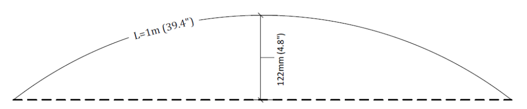
Excessive bending must be avoided when handling the modules. The module may be handled by the edge, but only if it is held vertically and without exerting excessive pressure to the edges of the cells.
Uninstalled modules or modules in removable installations must not be walked on.
If sharp or heavy objects are allowed to fall onto the modules, they can cause fractures in the cells.
If, during installation or maintenance, it is necessary to kneel on the module, it is advised to use foam cushions or soft knee pads, to avoid damaging the cells.
PHYSICAL INSTALLATION
INSTALLATION WITH FASTENERS
Small Solbian panels may be attached to a rigid surface using fasteners. For panels 100W and larger, we strongly recommend installing with optional backside peel and stick adhesive which allows small movement of the panel during times of heat expansion. (See section below on adhesive installation.) If the installation must be done with fasteners, the modules cannot be walked on (except for the SR+) and extreme care must be taken during installation to account for heat expansion. The fasteners should be at least ¼” from the edge of the panel and any part of the cell or wiring. The hole in the panel must be 1.5 x the diameter of the fastener and it is recommended that the hole is created with a punch rather than a drill to avoid heating the plastic. Install a rubber or teflon washer and a fender washer between the panel and the screw (the order of hardware from deck is – deck>panel>rubber washer> fender washer> screw). Be sure to appropriately bed the screw to properly seal the hole while still allowing room for movement due to heat expansion. Also, be sure not to over- tighten fasteners creating excessive bend in the panel at the site of the screw. If mounting multiple panels adjacent to each other, make sure to leave a 2-3mm gap between the panels, also to allow for heat expansion. Seal this gap with Sikasil WS-605-S, or a similar silicon-based product.
PICTURE FRAME INSTALLATION
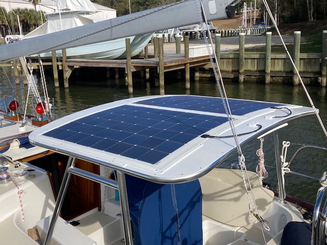
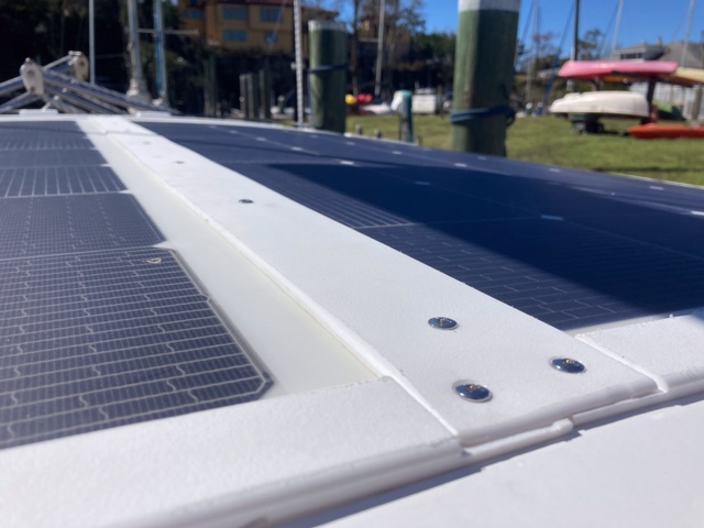
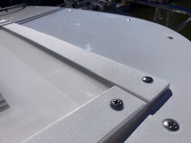
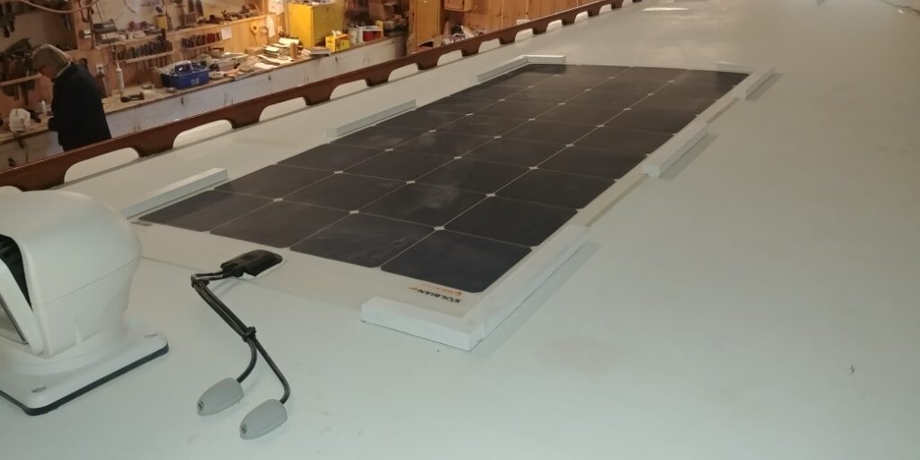
An alternative for mechanical fastening is the ‘Picture Frame’ method. Using starboard, or wood, create a rabbeted frame that captures all four edges of the panel, but still allows it to move with heat expansion. This frame is then fastened to the surface, and the panel ‘floats’ inside of the frame. See images below.
INSTALLATION ON A CANVAS BIMINI OR DODGER USING VELCRO, ZIPPERS, Luff Tape (Keder Rail), or Snap Locks
Although Solbian solar panels are ideal for canvas installation, they must be fully supported for their entire area. The canvas bimini or dodger surface must be firm and sturdy, and some older structures may need to be updated or re-tensioned. It is necessary to prevent any “flogging” in the wind or any excessive movement. One should be able to pull firmly on any corner of the structure and not produce much movement.
Solbian panels are “semi-flexible”, not folding or rollable. They can be mounted on curved surfaces if they do not exceed a bend with radius of 1m. Nor may they be installed in such a manner that may bend locally or have any kink, such as over a middle support bar in a bimini.
If the bimini is exceptionally large a stiffening backing can be added under the panel. Typically, a lightweight twin-wall polycarbonate may be used. The panel can be sewn to this backing material, but it is not recommended to use factory adhesive to fix it to the backing in order to allow for heat expansion of the panel.
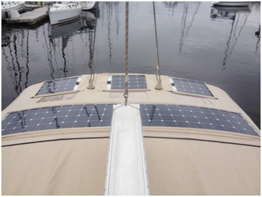
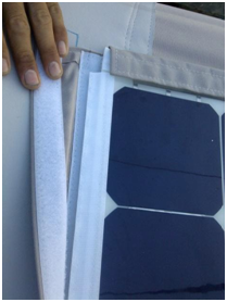
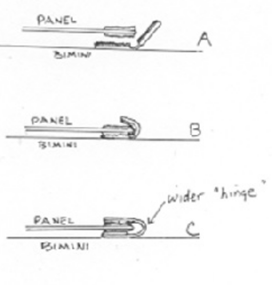
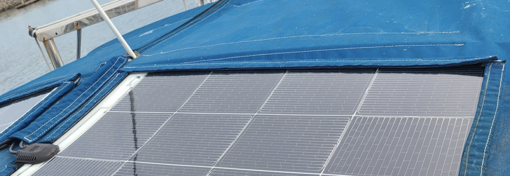
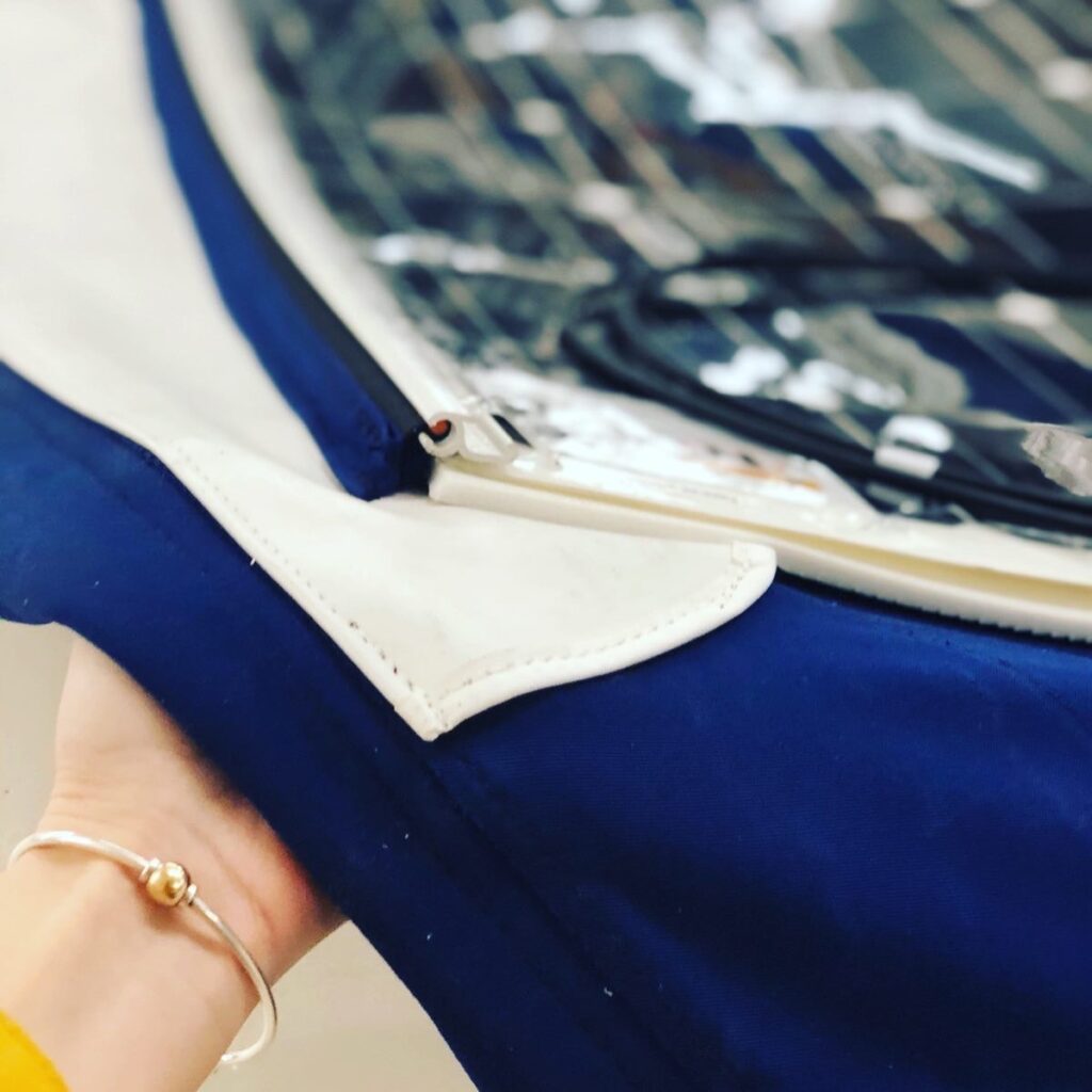
Regarding sewing, the plastic trim can be sewn through but do NOT sew into the cells. Stay 8-10mm (.4”) away from the cells. Stitching should have wide spacing. If holes are too close together, it can weaken the edge of the panel. Use 22-23 needle, diamond point. If installing velcro, use 1″ Polyester velcro top and bottom, to encapsulate the panel. Leave room for water to escape.
INSTALLATION USING FACTORY ADHESIVE, DOUBLE-SIDED VHB TAPE OR DUAL-LOCK TAPE
Before installation, the surface onto which the modules are to be installed must be perfectly clean and dry. If the panel will be walked on, it is imperative to use the factory peel and stick adhesive except for low traffic installations of the SR+ panels. The panel can be installed on a non-skid surface if the pattern is small and uniform and there are no other irregularities. The installation of Solbian modules using peel and stick adhesive supplied by the manufacturer must be carried out carefully and with precision (see below), as this permanent method does not allow repositioning. (Link to website installation video)
Recommended temperature for this installation is between 10-40°C (50-104°F). It should not be done in a very humid environment.
If the panel is not to be walked on, the surface on which the modules are installed does not necessarily need to be regular, and VHB tape or previously discussed mechanical fastening methods can be used.
For installation with factory supplied peel and stick adhesive, first draw the outline of the module on the rigid surface where the module is to be mounted (roof of boat, camper, etc.). Masking tape can also be used to mark the outline of the module. If using backside wiring, position the module first and insert the cables and grommet through the holes. Then peel back part of the double-sided adhesive backing, starting from the short side nearest the electrical contacts. Now, after being sure of the right position of the module, start fixing the short side on the area, this will allow you to proceed without losing alignment. Then lift the module from the opposite side to the one already set (without bending excessively), remove the adhesive film and proceed 20-30 cm at a time, making sure that the module adheres to the surface.
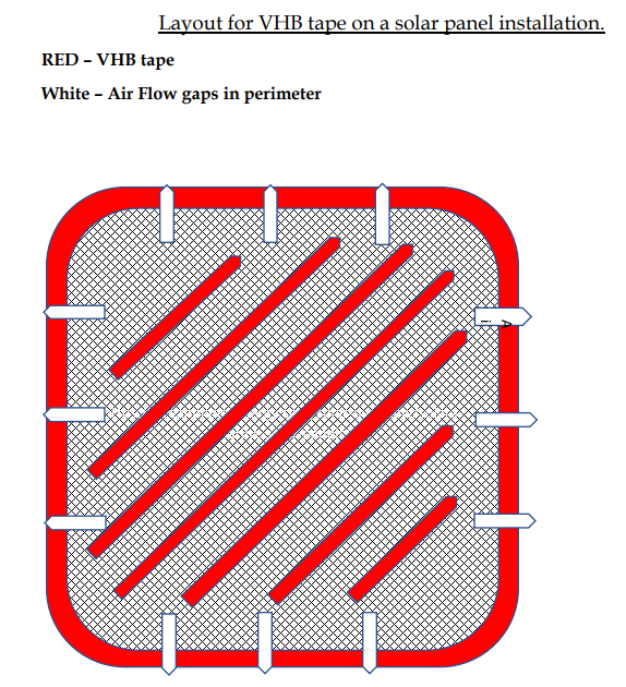
When using VHB tape, we recommend mounting with no more than 8” between each strip of tape to ensure secure attachment. It is also important to leave small gaps in the edges of the VHB tape to allow any moisture to escape, so no bulging of the panels will occur.
Before proceeding with a semi-permanent installation using double-sided tape, we recommend that you check the performance of the module by measuring Voc and Isc and comparing with the datasheet.
For panels that have been mounted with the factory adhesive, it is an option for both cosmetic reasons as well as protection of the panel edges to seal the edges of the panels to the mounting surface with a flexible sealing product such as Sikasil WS-605-S.
If mounting multiple panels adjacent to each other, make sure to leave a 4-5mm per 30″ of length gap between the panels to allow for heat expansion of the panel. So, if the panel is 30″ wide, have a 4-5mm gap on the long side and if the panel is 60″ long, leave 8-10mm gap on the short side. If the edges will be sealed as mentioned above, that will allow plenty of space for expansion.
(Note: The Solbian supplied factory adhesive is composed of the following: Acrylate Adhesive>Polyurethane Foam Black>Acrylate Adhesive)
ATTENTION: The double-sided adhesive backing makes a very strong bond with the support material and does not allow repositioning. Trying to remove a module, even if it is only partially attached, can seriously damage the cells.
When using Dual-Lock tape, we recommend using 3M dual-lock MP3560 tape (or similar product, meant for outside use and resistant to higher temperatures) mounted with no more than 8” between each strip of tape to ensure secure attachment.
INSTALLATION OF MODULES WITH BACK SIDE WIRING

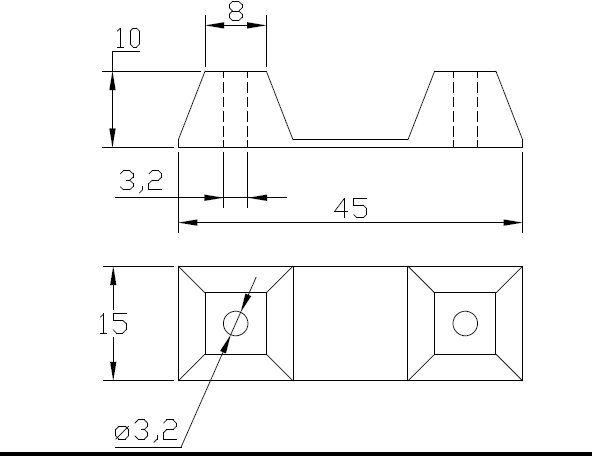
(Measurements in mm)
Your module may have wires exiting the back of the panel. These are electrical contacts and therefore, are live when the module is exposed to light. Although the voltage is low, avoid short-circuiting the contacts for extended periods of time which could lead to arcing and overheating. For this type of installation, we recommend that you have the modules installed by qualified marine technicians, respecting standards IEC 62548 and 62257 and/or ABYC electrical recommendations.
The cables can deteriorate due to repeated bending, so use clamps or other solutions to keep the cables fixed once the electric connections have been made.
Photovoltaic modules generate quite a high current, between 5A and 9A in full sunlight, therefore the junctions between the cables and the rest of the electrical installation must be made to high standards, to avoid overheating.
The back side wiring panels can be walked on but the installation must be performed using factory backside adhesive, taking care to apply the module on a smooth surface, as noted above on page 8.
Mark the position where the positive and negative cables will pass through the support. We recommend using a cardboard model of the module, with holes cut out for the cable positions. The grommets (wire exit supports) that protect the module’s cable exits have the dimensions shown on the side, so to obtain a surface adhering installation it’s recommended to make two 22 mm diameter holes or only one with larger dimensions (for instance 50×20 mm).
The grommet already provides the necessary electrical insulation and therefore it is not necessary to use silicone or other products to seal the hole. To avoid the risk of water stagnation and to facilitate the drying in case of splashing or condensation leave the grommet free in the hole.
PROTECTIVE FILM ON FRONT OF MODULE
Solbian SP-JB panels, with a smooth surface, have a protective film on the front. We recommend that you remove this after the installation has been completed. In any case, the protective film must be removed before using the module for the first time. Failure to do so can cause permanent damage to the panel that is not covered under warranty – essentially, the sun will bake the protective cover onto the panel.
The Solbian SP-series with a textured surface and the SR+ panels do not have a protective film on the surface.
ELECTRICAL INSTALLATION
OVERVIEW of the System
A photovoltaic module behaves like a current generator (such as a battery) and therefore has a positive contact and a negative contact.
Normally, the module cannot supply an electrical device directly, due to the variability of the current which depends on the intensity of the sunlight. It is therefore standard practice to use the module to charge a battery, which then supplies current to the devices.
A battery may only be charged directly by the photovoltaic module if the voltage is exactly right for the chosen battery (e.g. 14.4v charge voltage for a 12V lead-acid battery). However, this set-up is at risk of overcharging and is inefficient. We therefore recommend the use of electronic charge controllers, which optimize the charging process. Solbian strongly recommends using charge controllers with MPPT (Maximum Power Point Tracking), to exploit the maximum amount of energy possible.
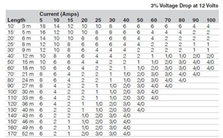
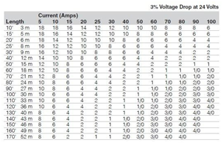
The cables must be of sufficient cross-section to avoid significant voltage-drop. Always use specific cable for photovoltaic installations, resistant to atmospheric agents. The cross-section (wire size) must be chosen considering the cable length (distance of run X 2 because it is a loop), 3% Voltage drop, and max current. The following tables show recommended wire size. Note: The SP panels have a max current of 5.5A, SR panels have a max of 8.5A and the SXp panels have a max current of 8A.
EXAMPLES OF INSTALLATIONS -Series, parallel, & multiple panels
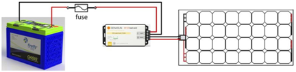
a) One single module with a charge controller, battery, and load. The load can be supplied directly by the controller (when the model of controller allows) or by the battery. In this arrangement, the controller needs to be able to handle the full rated current and voltage of the panel. The cable to the battery needs to be able to handle the maximum current of the controller. The fuse needs to be sized for 1.5 X the max current of the controller.
b) With several modules, the best solution is to connect each one independently to a separate controller. The controllers can then be connected in parallel to the battery, as they are protected against reverse current. Each controller should be sized for the individual panel ratings. When the controllers are connected in parallel, the total current to the battery is the sum of each controller’s max current. The size of the cable to the battery must be calculated by adding together the max currents of each controller and the fuse must be sized for 1.5 X the sum of the max currents.
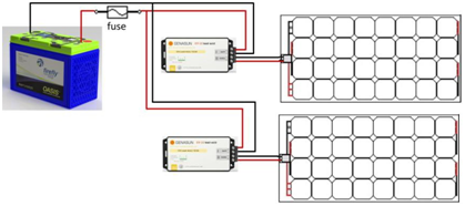
c) Multiple modules may be connected in series to a single controller. Only modules with the same current (i.e. same cell type) can be connected in series. The controller needs to be sized for the total wattage of all the panels, the total of all panel voltages and the current rating of an individual panel. The cabling to the battery needs to be able to handle the rated current of the controller and the fuse should be sized for 1.5 X the max current of the controller. This arrangement should only be used when shading or partial shading is NOT an issue. If any portion of either panel is shaded, it will affect the performance of the entire array.
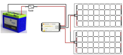
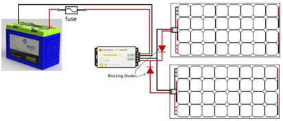
d) Multiple panels can be connected in parallel to a single controller. This should be done when shading is anticipated and if installing one controller per panel is not possible. Only panels of the same voltage(size)may be wired in parallel. In order to avoid wasted energy, overheating and +even fires, it is essential to use blocking diodes with parallel connections (see circuit diagram). Expect .7 V drop across the diodes. In this case, the controller should be sized for the voltage of the panel and the max current of all panels combined. The cabling should be sized for the max current of the controller and the fuse should be rated for 1.5 X the max current of the controller.
The choice of charge controller depends on the configuration of the installation, the type of modules and the battery. If you purchase your charge controller together with Solbian modules, you will receive the necessary assistance in choosing. In any case, Solbian will not be held responsible for damage or malfunctioning caused by incorrect use of a charge controller, whether purchased from Solbian or not. Make sure that you read the controller’s instructions very carefully.
ASSEMBLY OF MC4 CONNECTORS
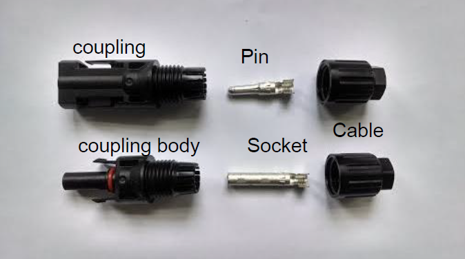
Note: The couplings supplied on Solbian solar panels are high quality industry standard MC 4 connectors. See above photo to properly match up the metal fitting with the appropriate coupling body. When making your connections, make sure that the positive (+) side of the panel is connected to the positive (+) side of the controller. In order to confirm the + and – cables from the panel, use a voltmeter. If the voltage reads positive, then the red side of your voltmeter is on the positive cable. If your voltmeter reads negative, then the red side of your voltmeter is on the negative cable.
1. Unscrew cable clamp from coupling body. Inside the “teeth” on the cable side of the coupling body you should see a black rubber gland. In most cases this will be set into the teeth when you receive it. If it is separate, as shown below, set it into the coupling body inside the teeth.
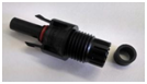
2. Strip end of cable approx. 1/2” and mate it with the winged end of the pin or socket. Squeeze wings of Pin or Socket down to restrain the portion of wire that has been stripped. Then solder where the wings of the pin pinch the bare wire. Note: The insulation should not be inside the wings of the pin but should come fairly close to the wings.
3. Slide Cable Clamp over cable then push Pin or Socket into respective Coupling until it clicks into place. Pull on wire to confirm correct engagement.
4. Tighten Cable Clamp onto Connector body.
MAINTENANCE OF THE PHOTOVOLTAIC SYSTEM
Due to the absence of moving parts, the required maintenance is minimal. The following instructions are important:
Keep the modules clean. Ensure there is nothing on the panel that could cause any shading on any of the cells as this can cause loss of output and excess heat that can damage the panel if extreme. Wash with fresh water, especially in a marine environment, to avoid damage caused by saltwater. The surface of the modules may be cleaned using neutral soap and water, wiping carefully and without using abrasive material. Denatured alcohol (methylated spirit) can be used to remove grease etc. When panel is clean and dry, apply a coating of a plastic protectant such as “RejeX” or Novus plastic cleaner #1- available at your marine chandlery or online. If contaminants build up or oxidation occurs over time, it may be necessary to polish the panel. The recommended polisher is Novus brand polish, #2 (Fine scratch remover). It is recommended that you hand polish the panels as a power polisher could burn the surface with too much friction. Follow the instructions on the product label.
Check the structural integrity of the installation and the electrical connections periodically.
Check the efficiency of the system using the monitoring functions in the charge regulators (LEDs or displays).
POSSIBLE FAILURE MODES
Fractured cells
Fracturing can be caused by excessive bending of the module during installation or use, or by impact or mechanical stress. Fractured photovoltaic cells do not normally cause a total loss of performance in a module, but more usually a drop in efficiency. A module with fractured or malfunctioning cells can be detected by measuring the current using a 10A ammeter. In full sunlight, the current should be the same order of magnitude as the Isc of the module (see datasheet), e.g. above 5A for the SP series modules. The voltage is barely affected by cell fracture.
Water inside the junction box
Although the junction boxes on the SP, SR & SXp are waterproof, infiltrations are possible due to manufacturing defects or impact. If this occurs, remove the cover of the junction box and proceed to dry the inside. Additionally, if any tension is applied to the cables, over time the junction box can work loose. The SR+ is manufactured with a different junction box which should never be opened or removed and is not at risk of having water infiltration.
Defects with the charge controller
Charge controllers, like all electronic devices, can fail. The display, if there is one, may indicate failure. In any case, the first step is to check the state of the electrical connections between modules, controllers, and batteries.
Hot-Spots
A module containing damaged cells, or even a module in good condition in which one or a small number of cells are completely shaded, can suffer from a HOT-SPOT, i.e. local overheating, even up to the point of causing the protective material to smoke and reach temperatures over 200°C (392 °F) on small areas.
In principle, this phenomenon could cause a fire, a danger which is always present where electrical apparatus is used. However, normally the damage is limited to small local burning.
In the event of HOT-SPOTS forming, the module must be disconnected immediately. In this way, the flow of current is stopped, and further temperature rises are avoided. As an alternative, it is possible to cover the module, to avoid exposure to light. In the case of several modules connected in series, the only solution is to disconnect the module.
EXCERPT FROM WARRANTY TERMS
Solbian modules are covered by a warranty for manufacturing defects and performance. Here are some of the warranty conditions. The text of the full warranty (the sole applicable warranty) is available on request and is published on the website www.solbian.eu and www.merlinsolar.com for the SR+.
Limited Product Warranty ‐ Five Years Repair, Replacement or Refund Remedy
SOLBIAN warrants its Photovoltaic Solar Modules (MODULES), including factory‐assembled DC connectors and cables, if any, to be free from defects in materials and workmanship under normal application, installation, use and service conditions. If MODULES fail to conform to this warranty, during the period ending Sixty (60) months from the date of sale to OceanPlanet Energy, SOLBIAN will, at its option, either repair or deliver a new product, or refund the purchase price. The repair or delivery or refund remedy shall be the sole and exclusive
remedy provided under the “Limited Product Warranty” and shall not extend beyond the Sixty (60) months period set forth herein. This ‐Limited Product Warranty‐ does not warrant a specific power output, which shall be exclusively covered under clause 2 hereinafter (Limited Peak Power Warranty).
Limited Peak Power Warranty ‐ Limited Remedy Five years
If, within a period of (5 ) five years from the Sales Date any MODULE(s) exhibits a power output less than 85 % of the minimum‐ Peak Power at STC ‐ as specified as of the Sales Date in SOLBIAN Flash Report, provided that such loss in power is determined by SOLBIAN ( at its sole and absolute discretion ) to be due to defects in material or workmanship, SOLBIAN will, at its sole option, either (1) replace such loss in power by either (a)providing additional MODULES to the CUSTOMER to make up for such loss in power or (b) replacing the defective MODULE(s) at the option of SOLBIAN or Merlin
RECYCLING AND DISPOSAL
Solbian is part of the European consortium PV-CYCLE, for the recycling of damaged or end-of-life modules, available in many European countries. Solbian photovoltaic modules are electrical apparatus and must be disposed of according to the laws of the country. In case of disposal requirements, please contact our sales department.